Difference Between 2 Wire RTD, 3 Wire RTD, and 4 Wire RTD — Complete Guide with Wiring Diagrams
If you’ve ever specified an RTD sensor and come across options like “PT100 2-wire”, “PT100 3-wire”, or “PT100 4-wire” — you already know how confusing this can be, especially when your supplier asks which configuration you need and you’re not sure of the difference.
This guide from Aavad Instrument Pvt. Ltd. — a leading RTD sensor manufacturer in Ahmedabad, Gujarat — explains everything you need to know about 2-wire, 3-wire, and 4-wire RTD connections: how they work, why the wiring matters, how to read the diagrams, and most importantly — which one you should specify for your application.
What is an RTD Sensor? (Quick Refresher)
An RTD (Resistance Temperature Detector) is a precision temperature sensor that measures temperature by exploiting the predictable relationship between temperature and the electrical resistance of a pure metal — most commonly platinum.
The most widely used RTD type is the PT100 — where “PT” stands for platinum and “100” indicates the sensor has a resistance of exactly 100 ohms at 0°C. As temperature increases, resistance increases in a known, repeatable, and highly linear fashion defined by the IEC 60751 standard.
Another common variant is the PT1000, which has a resistance of 1000 ohms at 0°C — offering a larger signal and reduced sensitivity to lead resistance (more on this below).
RTDs are preferred over thermocouples for:
- High accuracy requirements (pharmaceutical, food, laboratory)
- Temperatures below 600°C
- Long-term stability and repeatability
- Process control where calibration traceability is required
Now — here is the critical point that most engineers miss when they first work with RTDs:
The RTD element itself is not the only resistance in the measurement circuit. The connecting wires (lead wires) also have resistance — and this lead wire resistance causes measurement errors if not properly compensated.
This is the entire reason why 2-wire, 3-wire, and 4-wire configurations exist.
Why Lead Wire Resistance Causes Temperature Measurement Error
To understand the three wiring configurations, you first need to understand the problem they are solving.
A PT100 RTD has a temperature coefficient of approximately 0.385 Ω per °C near room temperature. This means:
- At 0°C → 100.00 Ω
- At 1°C → 100.385 Ω
- At 100°C → 138.50 Ω
Now consider this: a typical copper connecting cable has a resistance of approximately 0.017 Ω per metre per conductor (for 1.0 mm² cable). A 10-metre cable run has two conductors in series with the RTD element, adding approximately 0.34 Ω of unwanted resistance to the measurement circuit.
The measuring instrument cannot distinguish between resistance from the RTD element and resistance from the lead wires. It interprets all resistance as temperature — so that 0.34 Ω of lead resistance causes an error of approximately +0.88°C in the temperature reading.
For a pharmaceutical validation sensor, a cold storage monitor, or a process control loop with a tight temperature setpoint, this is an unacceptable error. And it gets worse with longer cables, smaller wire gauges, or higher ambient temperatures that increase cable resistance further.
The three RTD wiring configurations are three different engineering solutions to this problem.
2-Wire RTD — The Simplest Configuration
How a 2-Wire RTD Works
In a 2-wire RTD connection, the resistance temperature detector element is connected to the measuring instrument (transmitter, PLC input card, or indicator) using just two wires — one to each end of the RTD element.
The total resistance measured by the instrument is:
R(measured) = R(RTD element) + R(lead wire 1) + R(lead wire 2)Since the instrument measures the sum of all three resistances and interprets all of it as RTD resistance — and therefore as temperature — the lead wire resistance directly adds to the temperature reading as a positive error.
2-Wire RTD Wiring Diagram
  RTD SENSOR                     MEASURING INSTRUMENT
  ┌─────────┐                    ┌──────────────────┐
  │         │────── Wire 1 ──────│ Terminal 1       │
  │ PT100   │                    │                  │
  │ Element │────── Wire 2 ──────│ Terminal 2       │
  │         │                    │                  │
  └─────────┘                    └──────────────────┘

  Lead resistance of Wire 1 + Lead resistance of Wire 2
  = Both added directly to measured resistance = MEASUREMENT ERROR
2-Wire RTD: Advantages
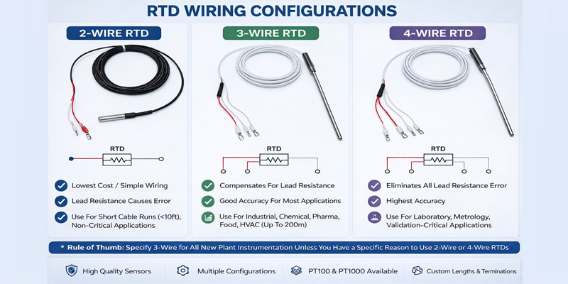
✅ Simplest wiring — only 2 conductors needed ✅ Lowest cost — minimal cable, simplest head terminal block ✅ Easiest to install — no risk of wiring mistakes ✅ Suitable when accuracy is not critical
2-Wire RTD: Disadvantages
❌ No lead resistance compensation — measurement error increases with cable length ❌ Not suitable for long cable runs (>3 metres typically) ❌ Accuracy degrades further if cable resistance changes with ambient temperature ❌ Not acceptable for high-accuracy applications (pharma, food, laboratory)
2-Wire RTD: When to Use
A 2-wire RTD is acceptable only when:
- The cable run between the sensor and instrument is short (under 3–5 metres)
- The application requires only moderate accuracy (±1°C or worse is acceptable)
- The sensor is mounted directly on the transmitter (head-mounted transmitter with zero cable length)
- Cost minimization is the primary driver and accuracy is secondary
Typical applications: Simple temperature indicators, short-run sensor-to-transmitter connections where the transmitter is head-mounted, non-critical process monitoring.
3-Wire RTD — The Industrial Standard
How a 3-Wire RTD Works
The 3-wire RTD is by far the most common configuration in industrial process plants and is the industry standard for process instrumentation worldwide.
In a 3-wire connection, a third wire is added to one end of the RTD element. The measuring instrument uses this third wire to measure the resistance of one lead wire and mathematically subtracts it from the total measurement — effectively compensating for lead resistance and eliminating most of the measurement error.
The key assumption the instrument makes is that all three lead wires have equal resistance — which is true when all three conductors are the same gauge, same material, and same length (as they are in a standard 3-core RTD cable).
The total resistance measured by the instrument is:
R(compensated) = R(RTD element) + R(lead 1) - R(lead 3) ≈ R(RTD element)If all three leads have equal resistance, the compensation is perfect. In practice, a small residual error remains due to minor differences between the conductors — but this is typically less than 0.1°C for most industrial cable runs.
3-Wire RTD Wiring Diagram
  RTD SENSOR                          MEASURING INSTRUMENT
  ┌─────────┐                         ┌───────────────────┐
  │         │───── Wire 1 (Red) ──────│ Terminal 1        │
  │ PT100   │                         │                   │
  │ Element │───── Wire 2 (White) ────│ Terminal 2        │
  │         │                         │                   │
  │         │───── Wire 3 (White) ────│ Terminal 3        │
  └─────────┘                         └───────────────────┘

  Wire 1: One end of RTD element + carries current
  Wire 2: Other end of RTD element + carries current
  Wire 3: Second connection to Wire 1 end — for resistance measurement only

  Instrument measures R(W1) + R(RTD) + R(W2) and separately R(W3)
  Assumes R(W1) = R(W3) and subtracts → lead resistance compensated
Standard Wire Color Codes for 3-Wire RTD
| Standard | Wire 1 (Element End A) | Wire 2 (Element End B) | Wire 3 (Element End A) |
|---|---|---|---|
| IEC 60751 | Red | White | White |
| DIN | Red | White | White |
| BS (UK) | Red | White | White |
| US (ANSI) | Red | White | White |
Important installation note: Always use the same cable throughout — never splice different cable types or gauges between the sensor and the instrument. This will destroy the lead resistance balance and introduce errors.
3-Wire RTD: Advantages
✅ Lead resistance compensated — significant improvement over 2-wire ✅ Industry standard — all industrial transmitters and PLC cards support 3-wire input ✅ Good accuracy for most industrial applications ✅ Works well for cable runs up to 200 metres with matched conductors ✅ Economical — only one extra conductor versus 2-wire ✅ Widely understood — minimal risk of wiring errors by field technicians
3-Wire RTD: Disadvantages
❌ Compensation is not perfect — assumes identical lead resistance, which is only approximately true ❌ Residual lead resistance error possible if conductors are not perfectly matched ❌ Not suitable for highest-accuracy metrology or validation applications
3-Wire RTD: When to Use
A 3-wire RTD is the correct choice for virtually all standard industrial process applications:
- Cable runs from 5 metres to 200 metres
- Accuracy requirement of ±0.3°C to ±1°C is sufficient
- Chemical plants, pharmaceutical processes, food manufacturing, HVAC, power plants, water treatment
- Any application using a standard 4–20 mA temperature transmitter
Specification tip: When ordering a 3-wire RTD, always specify that the three leads must be in the same cable (not field-extended with different cable types).
4-Wire RTD — The Highest Accuracy Configuration
How a 4-Wire RTD Works
The 4-wire RTD (also called a four-wire Kelvin connection or 4-wire PT100) completely eliminates lead resistance error — not by compensating for it (like the 3-wire method), but by removing it from the measurement circuit entirely using Kelvin sensing.
In a 4-wire connection, two wires connect to each end of the RTD element — giving four wires total. The instrument applies a precisely controlled excitation current through one pair of wires (the “current” or “force” wires), and measures the voltage drop across the RTD element using the second pair of wires (the “sense” or “voltage” wires).
Because the voltage sense wires carry virtually no current (a high-impedance voltmeter input), there is no significant voltage drop across the sense lead wires — meaning the voltage measured is purely across the RTD element, completely independent of lead resistance.
Using Ohm’s Law (R = V / I), the instrument calculates the true RTD resistance with no lead resistance contamination at all.
4-Wire RTD Wiring Diagram
  RTD SENSOR                                MEASURING INSTRUMENT
  ┌─────────────┐                           ┌─────────────────────┐
  │             │──── Current Wire 1+ ──────│ I+ Current Source   │
  │   PT100     │                           │                     │
  │   Element   │──── Sense Wire 1+ ────────│ V+ Voltmeter Input  │
  │             │                           │                     │
  │             │──── Sense Wire 2- ────────│ V- Voltmeter Input  │
  │             │                           │                     │
  │             │──── Current Wire 2- ──────│ I- Current Source   │
  └─────────────┘                           └─────────────────────┘

  Current flows through: I+ → RTD Element → I−
  Voltage sensed across: V+ → (RTD Element only) → V−
  Lead resistance of sense wires: NOT measured (zero current, zero voltage drop)
  Result: R(measured) = R(RTD element) exactly — NO lead resistance error
Standard Wire Color Codes for 4-Wire RTD
| Wire | Function | Typical Color |
|---|---|---|
| Wire 1 | Current+ (Force+) | Red |
| Wire 2 | Sense+ (Voltage+) | Red |
| Wire 3 | Sense− (Voltage−) | White/Blue |
| Wire 4 | Current− (Force−) | White/Blue |
4-Wire RTD: Advantages
✅ Zero lead resistance error — the gold standard for accuracy ✅ Works perfectly regardless of cable length or conductor resistance ✅ Required for metrology, calibration laboratories, and validation-critical applications ✅ Unaffected by changes in ambient temperature affecting cable resistance ✅ Best choice for PT100 Class AA sensors where full accuracy must be realized
4-Wire RTD: Disadvantages
❌ Requires 4-conductor cable — higher cable cost ❌ More complex wiring — higher risk of connection errors ❌ Not all field instruments support 4-wire input (most standard transmitters are 2-wire or 3-wire) ❌ Higher cost overall — only justified where the accuracy benefit is needed
4-Wire RTD: When to Use
A 4-wire RTD is required or recommended when:
- Maximum accuracy is essential — pharmaceutical validation, GMP, FDA requirements
- Calibration and reference standards work — metrology laboratories
- Long cable runs where even 3-wire residual error is unacceptable
- PT100 Class AA (1/10 DIN) sensors — where the full ±0.03°C accuracy must be preserved end-to-end
- Research and development, precision testing equipment
- PT1000 sensors in 2-wire configuration can achieve similar accuracy to 4-wire PT100 (PT1000’s higher resistance reduces the impact of lead resistance proportionally)
Head-to-Head Comparison: 2-Wire vs 3-Wire vs 4-Wire RTD
| Feature | 2-Wire RTD | 3-Wire RTD | 4-Wire RTD |
|---|---|---|---|
| Number of conductors | 2 | 3 | 4 |
| Lead resistance compensation | None | Partial (assumed equal) | Complete (Kelvin method) |
| Accuracy | Lowest | Good (industrial standard) | Highest |
| Typical error (10m cable) | ~0.88°C | <0.1°C | 0°C (eliminated) |
| Max cable run | <5 m | Up to 200 m | Unlimited |
| Cost | Lowest | Medium | Highest |
| Complexity | Simple | Moderate | Most complex |
| Instrument compatibility | All | All industrial | Requires 4-wire input |
| Best use case | Short runs, non-critical | Standard process industry | Lab, pharma validation, metrology |
| IEC 60751 Class achievable | Class C or worse | Class A / B | Class AA / A |
How Lead Wire Resistance Error Grows with Cable Length
The table below shows how much temperature error a 2-wire RTD introduces at different cable lengths using a standard 1.0 mm² copper cable (approximately 0.017 Ω/m per conductor):
| Cable Length | Lead Resistance (both wires) | Temperature Error (2-wire) |
|---|---|---|
| 1 m | 0.034 Ω | ~0.09°C |
| 3 m | 0.102 Ω | ~0.26°C |
| 5 m | 0.170 Ω | ~0.44°C |
| 10 m | 0.340 Ω | ~0.88°C |
| 20 m | 0.680 Ω | ~1.77°C |
| 50 m | 1.700 Ω | ~4.42°C |
| 100 m | 3.400 Ω | ~8.83°C |
Key takeaway: A 2-wire RTD on a 100-metre cable run introduces nearly 9°C of error. This would be catastrophic in any real process control application — yet it is a common mistake made by engineers who specify “PT100” without specifying the wiring configuration.
A 3-wire RTD on the same 100-metre run would reduce the residual error to <0.5°C (due to minor mismatches between lead wires). A 4-wire RTD would show zero error from lead resistance regardless of cable length.
How to Identify 2-Wire, 3-Wire, and 4-Wire RTD Sensors
When you receive an RTD sensor, you can identify its configuration simply by counting the wires coming out of the sensor connection head or terminal block:
| Number of wires | Configuration |
|---|---|
| 2 wires | 2-wire RTD |
| 3 wires | 3-wire RTD |
| 4 wires | 4-wire RTD |
For 3-wire RTDs per IEC 60751: 1 red wire connects to one terminal end of the element, 2 white wires connect to both the same end (one for current, one for sensing) and the other end respectively.
For 4-wire RTDs: 2 red wires (or red+red) and 2 white/blue wires, each pair connecting to the same element end.
Choosing the Right RTD Wiring for Your Industry
Pharmaceutical and Biotech (Ahmedabad / Vadodara, Gujarat)
→ Specify: 4-wire PT100 Class A or Class AA GMP and US FDA requirements demand the highest accuracy and traceability. Use 4-wire PT100 with NABL-traceable calibration certificates for autoclaves, bioreactors, freeze dryers, and validation-critical applications.
Chemical Industry (Ankleshwar / Dahej / Vapi)
→ Specify: 3-wire PT100 Class B or Class A Standard 3-wire PT100 in SS316 or Hastelloy sheath is the industry workhorse for reactor, heat exchanger, and distillation column temperature measurement.
Ceramic and Tile Kilns (Morbi, Gujarat)
→ Specify: Thermocouple (not RTD) for >600°C zones; 3-wire PT100 for cooling/exit zones RTDs are not suitable for kiln temperatures above 600°C. Use Type K or Type S thermocouples for high-temperature zones and PT100 RTDs for lower-temperature sections.
HVAC and Building Management
→ Specify: 3-wire PT100 or even 2-wire for short runs For HVAC duct sensors with short cable runs (under 5 metres), 2-wire PT100 is often acceptable. For central BMS systems with long cable runs, use 3-wire.
Power Plants and Utilities
→ Specify: 3-wire PT100 Class A in Inconel or SS316 with thermowell Turbine bearings, winding temperatures, and feedwater temperature monitoring all use 3-wire PT100 sensors. Duplex (dual-element) configurations are standard for redundancy.
Food and Beverage Processing
→ Specify: 3-wire PT100 Class A with hygienic process connection Tri-Clamp or DIN 11851 connections, electropolished SS316L sheaths, with 3-wire Class A accuracy meet HACCP and food safety requirements.
3-Wire RTD vs 4-Wire RTD: Which Should You Specify?
This is the most common question when engineers upgrade from 2-wire to higher accuracy configurations. Here is the practical decision guide:
Choose 3-wire RTD when:
- Your application requires ±0.3°C to ±1°C accuracy
- Cable runs are under 200 metres with matched conductors
- You are using a standard 4–20 mA head-mounted or rail-mounted transmitter
- Application is standard process control (chemical, HVAC, food, power)
- This covers 90%+ of all industrial RTD applications
Choose 4-wire RTD when:
- Your application requires ±0.1°C accuracy or better
- You are performing temperature validation (pharmaceutical, IQ/OQ/PQ)
- Cable runs are very long and accuracy cannot be compromised
- You are building a calibration reference or metrology instrument
- Your measurement instrument explicitly supports 4-wire Kelvin input
- This covers laboratory, pharma validation, and high-precision applications
Pro tip from Aavad Instrument: Even if you specify a 4-wire RTD sensor, make sure your transmitter or PLC input card actually has a 4-wire RTD input mode. Many standard 4–20 mA transmitters only accept 3-wire input and will not use the 4th wire even if it is connected. In that case, leave the 4th wire unconnected at the instrument end.
RTD Transmitter Wiring: How the RTD Connects to a 4–20 mA Transmitter
In modern industrial installations, RTD sensors are almost always connected to a temperature transmitter that converts the RTD resistance signal into a standardized 4–20 mA current loop for connection to a PLC, DCS, or SCADA system. This is far preferable to running the raw RTD signal over long cable distances.
A head-mounted 2-wire temperature transmitter sits inside the RTD terminal head and connects directly to the RTD element terminals. From there, only two wires carry the 4–20 mA signal to the control room — completely eliminating the lead resistance problem for long cable runs, regardless of whether the RTD itself is 2-wire, 3-wire, or 4-wire.
This is why head-mounted transmitters are the standard in modern process plants: the RTD cable (from element to transmitter) is just a few centimetres inside the head, so lead resistance is negligible, and the long run to the control room carries a noise-immune 4–20 mA signal.
Common RTD Wiring Mistakes to Avoid
❌ Using different cable types for different sections of the same RTD loop → Destroys lead resistance balance in 3-wire measurements
❌ Connecting a 3-wire RTD in 2-wire mode (ignoring the third wire) → Wastes the compensation capability; introduces lead error
❌ Assuming all white wires are the same in a 3-wire RTD → In a 3-wire RTD, there are 2 white wires (same element end) and 1 red wire. Swapping them causes a significant measurement error.
❌ Using undersized cable (small cross-section increases lead resistance per metre) → Always use minimum 0.5 mm² conductors for RTD wiring; 1.0 mm² preferred for runs over 50 m
❌ Running RTD cables in the same tray as power cables without shielding → RTD signals are low-level; electromagnetic interference from power cables causes signal noise. Always use shielded, twisted-pair cable and ground the shield at the instrument end only.
❌ Not verifying transmitter input mode matches RTD wiring → A transmitter configured for 3-wire input connected to a 2-wire RTD will give wrong readings.
PT100 vs PT1000: Does Wire Configuration Apply to Both?
Yes — the 2-wire, 3-wire, and 4-wire configurations apply to both PT100 and PT1000 RTD sensors.
However, PT1000 sensors have an important natural advantage: because the element resistance is 10 times higher (1000 Ω vs 100 Ω at 0°C), the same lead wire resistance represents a 10 times smaller percentage error in the measurement. This means:
- A PT1000 in 2-wire configuration can achieve similar lead-resistance-related accuracy to a PT100 in 3-wire configuration — making PT1000 sensors attractive where 3-wire or 4-wire cabling is difficult.
- PT1000 sensors are increasingly popular in building automation, HVAC, and non-industrial applications where 2-wire wiring simplicity is preferred without sacrificing accuracy.
Buying an RTD Sensor: What to Specify
When ordering an RTD temperature sensor from a manufacturer, always specify:
- Element type: PT100 (most common) or PT1000
- Accuracy class: Class AA (1/10 DIN), Class A (1/4 DIN), or Class B (1/2 DIN) per IEC 60751
- Wiring configuration: 2-wire, 3-wire, or 4-wire
- Sheath material: SS304, SS316, SS316L, Inconel 600, Hastelloy C-276
- Sheath diameter: 4 mm, 6 mm, 8 mm, 10 mm, 12 mm OD
- Insertion length (U-length): Distance the sensor tip must reach into the process
- Total length (L-length): Including connection head or neck
- Process connection: ½” NPT, G½”, M20×1.5, flanged, Tri-Clamp
- Head type: Terminal head (Form B, D, F), extension neck, flying leads, M12 connector
- Certifications: Standard, ATEX/IECEx (hazardous area), NABL calibration certificate
Why Aavad Instrument is Gujarat’s Preferred RTD Sensor Manufacturer
Aavad Instrument Pvt. Ltd., based in Ahmedabad, Gujarat, manufactures PT100 and PT1000 RTD sensors in all three wiring configurations — 2-wire, 3-wire, and 4-wire — for industries across India and international markets.
Our RTD sensors are trusted by:
- Pharmaceutical manufacturers in Ahmedabad and Vadodara
- Chemical plants in Ankleshwar, Dahej, and Bharuch
- Ceramic tile manufacturers in Morbi
- Food and beverage processors in Surat and Rajkot
- Power plants and utilities across Gujarat
- Water treatment authorities across India
What every Aavad Instrument RTD sensor includes: ✅ Manufactured to IEC 60751 standard ✅ Class A or Class B accuracy as specified ✅ Calibration certificate (NABL-traceable on request) ✅ Material Test Certificate (MTC) for wetted parts ✅ Dimensional drawing and datasheet ✅ 7–14 working day standard delivery ✅ Custom specifications accepted — special materials, ATEX, hygienic connections
📍 Factory in Ahmedabad, Gujarat | Pan-India supply | Export to Middle East, Africa, Southeast Asia
📞 Contact us for specifications, pricing, and technical support: 🌐 www.aavadinstrument.com 📧 info@aavadinstrument.com
Frequently Asked Questions — 2-Wire, 3-Wire, and 4-Wire RTD
FAQ 1: What is the main difference between 2-wire, 3-wire, and 4-wire RTD?
The main difference is how each configuration handles lead wire resistance. A 2-wire RTD adds full lead resistance to the measurement (highest error). A 3-wire RTD partially compensates for lead resistance (industry standard accuracy). A 4-wire RTD completely eliminates lead resistance using a Kelvin measurement technique (highest accuracy). For most industrial applications, 3-wire RTD is the recommended choice.
FAQ 2: Which RTD wiring is most commonly used in industrial plants?
The 3-wire RTD is the most commonly used wiring configuration in industrial process plants worldwide. It offers a good balance between accuracy and cost, and is supported by virtually all industrial temperature transmitters and PLC/DCS input cards. It is the standard specification for most chemical, pharmaceutical, food, power, and water treatment applications.
FAQ 3: Can I use a 2-wire RTD with a 3-wire transmitter input?
Yes, you can connect a 2-wire RTD to a transmitter with a 3-wire input by connecting the same terminal on the RTD to two of the transmitter’s three input terminals (shorting the jumper on the transmitter side). However, this eliminates the lead resistance compensation and the measurement will include full lead resistance error — so it is only acceptable for short cable runs or non-critical applications.
FAQ 4: Does a 4-wire RTD need a special transmitter?
Yes, to realize the accuracy benefit of a 4-wire RTD, the measuring instrument (transmitter, data logger, or PLC card) must have a 4-wire RTD input mode that uses the Kelvin measurement technique. Many standard head-mounted temperature transmitters only support 2-wire or 3-wire input. If you connect a 4-wire RTD to a 3-wire transmitter, only 3 of the 4 wires will be used and you lose the 4-wire accuracy advantage.
FAQ 5: What is the accuracy difference between a 2-wire and 3-wire RTD over a 10-metre cable?
Over a 10-metre cable run with standard 1.0 mm² copper conductors, a 2-wire RTD will have a lead resistance error of approximately +0.88°C. A 3-wire RTD on the same cable will have a residual error of typically less than 0.1°C (due to very minor conductor imbalance). A 4-wire RTD will have zero lead resistance error regardless of cable length.
FAQ 6: How do I identify the wires on a 3-wire PT100 RTD?
In a standard 3-wire PT100 RTD per IEC 60751, the wiring is: 1 red wire and 2 white wires. The red wire connects to one end of the platinum element. One white wire connects to the other end of the element (the measurement wire). The second white wire also connects to the same end as the red wire (the compensation wire). If you measure resistance: the two white wires together should give approximately 200 Ω + small lead resistance at 0°C; the red to either white gives approximately 100 Ω at 0°C.
FAQ 7: Is a 4-wire RTD required for pharmaceutical GMP validation?
Yes, generally. Pharmaceutical validation protocols (IQ, OQ, PQ) and GMP requirements under WHO, US FDA, and EU GMP guidelines require temperature measurement accuracy typically better than ±0.5°C — often ±0.1°C or better. To reliably achieve and demonstrate this accuracy with a traceable NABL calibration certificate, a 4-wire PT100 Class A or Class AA is the standard specification for validation-critical sensors.
FAQ 8: Can I convert my existing 3-wire RTD to 4-wire accuracy without replacing the sensor?
No. The number of wires is a physical property of the sensor — you cannot add a fourth wire if the sensor was only manufactured with three. However, if you use a head-mounted transmitter that converts the 3-wire RTD signal to a 4–20 mA output inside the terminal head (where cable length is negligible), you effectively eliminate lead resistance from the long cable run and can achieve near-4-wire accuracy in the overall system.
FAQ 9: What cable should I use for 3-wire RTD wiring?
Use shielded twisted-pair cable with all three conductors of the same cross-section (minimum 0.5 mm², 1.0 mm² recommended for runs over 50 metres). All three conductors must be in the same cable to ensure matched lead resistance for the compensation to work correctly. Ground the cable shield at the instrument end only (single-point grounding) to avoid ground loops.
FAQ 10: What is the PT100 resistance value at different temperatures?
A PT100 RTD (per IEC 60751) has the following resistance values at key temperatures:
| Temperature | PT100 Resistance |
|---|---|
| −200°C | 18.52 Ω |
| −100°C | 60.26 Ω |
| 0°C | 100.00 Ω |
| 25°C | 109.73 Ω |
| 100°C | 138.51 Ω |
| 200°C | 175.86 Ω |
| 300°C | 212.05 Ω |
| 400°C | 247.09 Ω |
| 600°C | 313.71 Ω |
FAQ 11: Where can I buy 3-wire PT100 RTD sensors in Ahmedabad or Gujarat?
You can buy 3-wire PT100 RTD sensors in standard and custom specifications from Aavad Instrument Pvt. Ltd., a manufacturer based in Ahmedabad, Gujarat. They supply Class A and Class B RTD sensors in SS316, Inconel, and Hastelloy sheaths with NABL-traceable calibration certificates, to industries across Gujarat and pan-India. Visit www.aavadinstrument.com or contact them directly for specifications and pricing.
FAQ 12: What is the difference between PT100 and PT1000 RTD in terms of wiring?
Both PT100 and PT1000 use the same 2-wire, 3-wire, and 4-wire connection principles. The key difference is that PT1000 (1000 Ω at 0°C) is 10 times more resistant than PT100, so the same lead wire resistance represents a 10 times smaller proportional error. This makes a 2-wire PT1000 approximately equivalent in lead resistance error to a 3-wire PT100 — making PT1000 attractive for simpler 2-wire installations where some accuracy improvement over a 2-wire PT100 is needed without additional wiring.
Conclusion
Understanding the difference between 2-wire, 3-wire, and 4-wire RTD configurations is fundamental to specifying, installing, and commissioning temperature measurement systems correctly in any industrial environment.
- 2-wire RTD: Use only for short runs and non-critical applications
- 3-wire RTD: The industry standard for the vast majority of process industry applications
- 4-wire RTD: Reserve for validation-critical, high-accuracy, or long-run metrology applications
When in doubt, specify a 3-wire PT100 Class A — it covers nearly every standard industrial requirement with good accuracy, reliable lead resistance compensation, and universal compatibility with industrial transmitters and control systems.
And when you need a trusted, ISO-certified RTD sensor manufacturer in Ahmedabad, Gujarat — Aavad Instrument Pvt. Ltd. is ready to supply exactly what your process requires, with complete documentation, competitive pricing, and fast delivery across India.
📞 Get Your RTD Sensor Quote Today 🌐 www.aavadinstrument.com 📧 info@aavadinstrument.com 📍 Aavad Instrument Pvt. Ltd., Ahmedabad, Gujarat, India