Resistance Temperature Detectors (RTD’s) – Platinum Wiring Configurations and Lead Wire Color Codes
Typical RTD Wiring Configurations and Aavad Color Codes
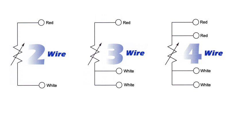
Two-Wire RTD (Red, White):
Aavad two-wire RTD is constructed with only one red and one white lead wire. This type of sensor is the least accurate form of RTD since it does not compensate for lead wire resistance. The total resistance of the lead wire will be added to the calibrated elements resistance. This will result in a higher temperature reading than is actually being measured. The error created by the lead wire can be quit substantial if it is not compensated. The two-wire RTD is the least common type of lead configuration.
Three-Wire RTD (Red, White, White):
Aavad three-wire RTD is constructed with two white lead wires and one red lead wire. This is the most common configuration for RTD sensors used today. The three-wire RTD is more accurate than the two-wire version since the instrument or transmitter can use this third lead to compensate for added resistance and ambient temperature changes along the lead length.
Four-Wire RTD (Red, Red, White, White):
Aavad four-wire RTD is constructed with two white lead wires and two red lead wires. lt is the most accurate RTD configuration since the instrument or transmitter can completely compensate for lead wire resistance and ambient temperature changes along with the leads. The four-wire RTD can also compensate for errors caused by mismatched lead wires (does not occur often). This is accomplished by passing a current through the outer leads (First Red + First White) and measuring the voltage drop across the inner leads (Second Red + Second White). The instrument or transmitter can then calculate the resistance of the element alone. These sensors are not as common as the three-wire version. They are only used where very high accuracy is critical. Four-wire RTDs can be used as a three-wire or two-wire by removing one of the red leads or one of the red and one of the white leads.


