Abstract: Temperature is a critical measurement system in iron making process, at Blast Furnaces. Many critical parameters like coke rate, tuyere velocity, refractories life of stoves etc. decide through this temperature measurement. This paper attempts to describe the installation of temperature sensors in Blast Furnaces to make reliable and safe operations. Furthermore, this installation method can be used in all areas where ceramic type thermocouples are used.
- Introduction
A Blast Furnace consists of four major sections.
- a) Blast Furnace Proper
- b) Charging System
- c) Gas Cleaning Plant
- d) Stoves
Hot blast stove is used for converting cold blast at 150 -200 degree C from blower to hot blast between 900 degree C to 1300 degree C. To ensure efficient furnace operation, the required flow-rate and temperature of the blast air must be maintained. Typical industrial flows are 3000-10000 Nm3 per minute at temperatures of 1000-1300 C, depending on the size and type of furnace. This hot air provides up to 40% of the blast furnace sensible heat requirement. Dome and Hot Blast Mains is the major section of Stoves where ceramic based thermocouples installed due to high temperature (1200-1300 degree Celsius). Dome Thermocouple is one of the main indices of the thermal performance of Blast Furnace Stoves.
Fig#1 Shows Stoves Process
Fig#2Dome Section of Stoves
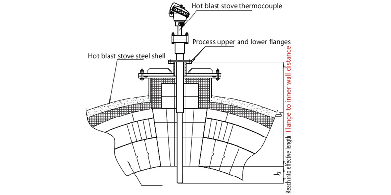
Fuel Combustion in the stoves is completed at the end of the combustion chamber and the maximum temperature develops under the dome. Standard stove designs provide for the installation of a thermocouple in the center of the
dome, in the vertical position (thermocouple in figs.3).

Figure 1: Stove Process

Figure 2: Dome Section of Stoves

Figure 3: Thermocouple in Dome Refractory
Thermocouple Installed in Stoves Dome at I Blast Furnace:
Fig.3 shows Stoves Dome at IBF have one thermocouple (Type “B”) and one pyrometer.“B” Type thermocouples are used for measuring high temperature (1200-1300 deg. C).

Same type of thermocouple used in Hot Blast Mains, which is used for the measurement of hot air temperature. If thermocouple shows in fig.3 gets damaged, then it is difficult to run the Stoves process. Same thermocouple if damaged in Hot Blast mains then blast furnace operation need to be stops immediately.
Failure Modes of Dome and Hot Blast Thermocouples:
Following failure modes
- a) Due to Improper Design.
- b) Due to completion of its life.
- c) Due to Thermal Shocks.
- d) Due to high vibrations.
- e) Due to hit by some foreign particle.
- f) Drift due to Shut Error.
In January 2016, IBF Stove Dome pyrometer changed with newly developed thermocouple same type and same make with some modifications in flange size and protection tube diameter. During installation of thermocouple, dome temperature was around 1150 deg. C. After 20 days from installation, the thermocouple was damaged due to above factors. (Fig.4)

Figure 4: Temperature Trends of Both Thermocouple after installation and during failure.
Identification of Root Cause and Developing Solution:
The damaged thermocouple was taken out in April 2017 shutdown, following observation were observed.

Figure 5: Damaged Thermocouple
- No mechanical damage was found on the tube.
- No mark or cracked was observed.
- Millivolt fluctuates very rapidly.
- Resistance is found in megaohms.
The damaged thermocouple send to Yamari Japan for further analysis. In Japan, Radiographic test (fig.6) was done to identify the main root cause of failure.

Figure 6: Radiographic Test on Damaged Thermocouple at Yamari Japan.
From Radiographic Test, it was proved that thermocouple was damaged and following things observed. The element was twisted and found open at tip position. Damage (Broke) of internal protection tube PT-0 and insulator was found.
Root Cause:
Thermal Shock. Thermal shock is occurred by stress affect the expand and contract by temperature difference between tip and stem of protection tube.
Why?
The reason of thermal shock was observed that the thermocouple was directly inserted into process condition. This means from 25 degrees ambient to 1200 degrees Celsius.
Counter Measure to avoid failure:
a) Modification in design on damaged thermocouple.
b) Installation procedure for ceramic based thermocouple developed.
Design Difference between Damaged and New Thermocouple

Installation Procedure
Install the tube slowly recommended 50mm/10min. For operating temperature 1350 degree Celsius and maximum of 1400 degree Celsius.

Figure 7: Installation of Dome Thermocouple at I Blast Furnace, Tata Steel Jamshedpur.
Marking on tube at a gap of 50mm throughout its length. Install the tube slowly 50mm/min with a gap of 10 mins. Approx. 3-4 hours was taking to install one thermocouple. Horizontal Deployment of Installation Procedure in HBF Dome and Hot Blast Thermocouple changing. Same Installation procedure can be deployed for F, G and KPO Blast Furnaces.

Figure 8: Temperature Trend during Thermocouple Installation
- Conclusion
After installation of thermocouple at different furnaces H and I the reliability of the measurement system improves.
- System Reliability Improvement.
- Equipment Life Increases.
- Maintenance Cost Reduces.
- Reduction in Spare Cost


