Electromagnetic flow meters (or mag meters) are a type of velocity or volumetric flow meter that operates pursuant to Faraday’s law of electromagnetic induction – which states that a voltage will be induced when a conductor moves through a magnetic field. Magmeters can detect the flow rate of conductive fluids only. Early mag meter designs required a minimum fluidic conductivity of 1-5 micro siemens per centimeter for their operation. The newer designs have reduced that requirement a hundredfold to between 0.05 and 0.1.
An insulating material lines a non-magnetic pipe that serves as the foundation of an electromagnetic flowmeter. A pair of electrodes are inserted into the pipe and its lining, and a pair of magnetic coils are positioned as depicted in Figure 1.
If a conductive fluid flows through a pipe of diameter (D) through a magnetic field density (B) generated by the coils, the amount of voltage (E) developed across the electrodes–as predicted by Faraday’s law–will be proportional to the velocity (V) of the liquid. Because the magnetic field density and the pipe diameter are fixed values, they can be combined into a calibration factor (K) and the equation reduces to:
E = KV
A signal-weighting factor adjusts for the velocities that change at various places along the flow profile. The magnetic coils are shaped so that the magnetic flux will be greatest when the signal weighing factor is lowest and vice versa, providing further compensation.
The K factor of each mag meter is determined by the water calibration of each flow tube. The resulting K value is applicable to any other conductive liquid and is linear across the whole flowmeter range. As a result, flow tubes are typically calibrated at only one velocity. Magmeters can measure flow in both directions because changing the polarity but not the amplitude of the signal changes the polarity but not the magnitude of the signal.

The K value obtained by water testing might not be valid for non-Newtonian fluids (with velocity-dependent viscosity) or magnetic slurries (those containing magnetic particles). These types of fluids can affect the density of the magnetic field in the tube. In-line calibration and special compensating designs should be considered for both of these fluids.
Magmeter Excitation
A millivolt signal is produced by the voltage that develops at the electrodes. At or near the flow tube, this signal is often transformed into a standard current (4-20 mA) or frequency output (0-10,000 Hz). Intelligent magnetic transmitters with digital outputs can be connected directly to a distributed control system. Because the mag meter signal is weak, the lead wire should be insulated and twisted if the transmitter is located a long distance away.
The coils of the mag meter can be powered by either alternating or direct current (Figure 2). Line voltage is applied to the magnetic coils when ac excitation is utilised. As a result, the flow signal (at constant flow) will similarly have a sine wave appearance. The wave’s amplitude is related to its velocity. Noise voltages can be created in the electrode loop in addition to the flow signal. Out-of-phase noise is easily filtered, but in-phase noise necessitates stopping the flow (with the pipe full) and setting the transmitter output to zero. The fundamental issue with ac mag meter designs is that noise varies with process conditions, necessitating regular re-zeroing to maintain accuracy.

A low frequency (7-30 Hz) dc pulse is utilised to excite the magnetic coils in dc excitation devices. The transmitter detects both the flow and noise signals when the coils are pulsed on (Figure 2). The transmitter only sees the noise signal in the intervals between pulses. As a result, the noise can be reduced continually after each cycle.
This ensures a consistent zero and eliminates zero drift. Aside from being more accurate and capable of measuring lower flows, dc meters are less bulky, easier to install, consume less energy, and are more cost-effective than ac meters. One new dc design consumes substantially more power than previous generations, resulting in a higher flow tube signal.
Another innovative design pulses the coils at 7 Hz for zero stability and at 70 Hz for a louder signal. This is known as a unique dual excitation method. Both ac and dc electricity can be used to power mag meter transmitters. There is also a two-wire, loop-powered, intrinsically safe dc magnetic flowmeter available, but due to power constraints, it performs less well.
Recently, pulsed ac meters have also been made available, solving the zero stability issues with conventional ac designs. As a result of the circuitry in these devices frequently disrupting the ac power, the effects of process noise on the output signal are automatically cancelled out.
Currently, dc excitation is employed in roughly 85% of installations, with ac mag meters claiming the remaining 15% when the following criteria are met:
- When a significant amount of air is entrained in the process stream;
- When the process stream is a slurry and the solid phase is not evenly mixed with the liquid or when the solid particle sizes are not consistent;
- Whenever the flow pulses at a frequency lower than 15 Hz.
- The output of a pulsed dc meter is likely to be noisy when any of the three criteria listed above are true. By filtering and dampening the output signal, one can occasionally reduce the noise issue (keep the fluctuations within 1% of the setpoint). It is always preferable to use an ac meter if damping for noise reduction is going to take longer than 1 to 3 seconds.
Flow Tubes, Liners, and Probes
The face-to-face dimensions of flanged flow tubes (lay lengths) usually meet the recommendations of the International Organization for Standardization (ISO). The dimensions of short form magmeters usually meet these guidelines as well. Magnetic flow tubes and liners are available in many materials and are widely used in all process industries, including food, pharmaceutical, mining, and metals.
When pry bars are used to install or remove liner materials from process pipes, some materials (especially PFA) might be harmed. They can also be destroyed if the flange bolts are over torqued. There are liner protectors available to assist prevent such damage.
In general, any flow tube can be used with any transmitter from the same brand. A 2-in. magnetic flowmeter can cost anywhere from $1,500 to $5,000, depending on its design and features. This cost has been decreasing, although it is still greater than the least priced flow sensors.
Magnetic flowmeters can also be packed as probes and placed through taps into process pipes. These probes are equipped with both electrodes and magnetic coils. The flowing process fluid causes a voltage to be generated at the electrodes, which represents the velocity at the probe tip rather than the average fluid velocity across the pipe. These retractable mag meters are affordable. As a result, the process does not need to be stopped to install or uninstall them. Metering accuracy is heavily reliant on the relationship between measured and average velocity in the pipe.
Electrodes
The electrodes in typical flow tubes are in touch with the process fluid. If a droplet of liquid platinum sinters through a ceramic liner and fuses with the aluminium oxide to form a flawless seal, it can be detachable or permanent. This design is favored due to its low cost, resilience to abrasion and wear, insensitivity to nuclear radiation, and suitability for sanitary applications due to the absence of voids where germs can thrive. The ceramic tube, on the other hand, cannot withstand bending, strain, or abrupt cooling, and it cannot withstand oxidising acids or hot and concentrated caustic.
Non-contacting electrodes are employed in a more contemporary capacitively coupled arrangement. Metal regions are placed between layers of liner material in these designs. They come in sizes less than eight inches in diameter and with ceramic liners. Magmeters equipped with these non-contacting electrodes can “read” fluids with 100 times the conductivity required to activate conventional flow tubes. These designs are also more suited for tough coating applications because the electrode is located beneath the liner.
Choosing an Electromagnetic Flow Meter
Magnetic flowmeters may measure the flow of liquids and slurries that are clean, multi-phase, unclean, corrosive, erosive, or viscous as long as their conductivity is greater than the minimum necessary for the specific design. If the flow velocity is greater than 1 ft/sec, the predicted error and rangeability of the best designs are 0.2-1% of the rate, spanning a range of 10:1 to 30:1. Even at flow rates below 0.1 ft/s, there is an increase in measurement error, but the values are still repeatable.
It is critical that the process fluid’s conductivity be uniform. If two fluids are blended and one of the additives has a significantly different conductivity than the other process fluid, it is critical that they are completely intermixed before the blend reaches the mag meter. The output signal will be noisy if the blend is not uniform. To avoid this, a static mixer installed upstream of the mag meter can minimize areas of variable conductivity.
The manufacturer’s published capacity tables or charts are used to calculate the size of the mag meter. A flow capacity nomograph for lines with 0.1 in. to 96 in. in diameter is shown in Figure 4-3. Flow rates should range from 3 feet per second to 15 feet per second for the majority of applications. The typical velocity range for corrosive fluids should be 3-6 ft/sec. Continuous running of the flow tube above the upper limit of the typical velocity range will shorten the life of the meter, while continuous operation below 3 ft/sec will result in a decline in metering accuracy.

The magmeter’s obstructionlessness reduces the chance of clogging and keeps the unrecovered head loss at the same level as a comparable length of straight pipe. Low pressure drop is preferred because it helps gravity feed systems and reduces pumping expenses.
Problem Applications
Because the mag meter cannot distinguish between entrained air and the process fluid, air bubbles will result in a high reading from the mag meter. The output signal will become noisy or even disrupted if the trapped air is not uniformly distributed and instead assumes the shape of air slugs or huge air bubbles (the size of the electrode). As a result, the meter should be sized so that the flow velocity under typical flow circumstances is 6–12 ft/sec in situations where air entrainment is likely.
Another common mag meter issue is electrode coating. Material accumulation on the meter’s inner surfaces can electrically separate the electrodes from the process fluid. This can result in a signal loss or a measurement inaccuracy by varying the width of the flow tube or producing span and zero shifts. Naturally, prevention is the best solution. One protective measure is to size the meter so that the flowing velocity is quite high under normal flow conditions: at least 6-12 ft/sec, or as high as practicable given the potential of erosion and corrosion.
Another technique of prevention is to utilise electrodes that protrude into the flow stream to benefit from turbulence and washing. A mechanical cleaning system can be installed and utilised sporadically or continuously in more severe service to remove coating and build-ups.
AAVAD Magmeters
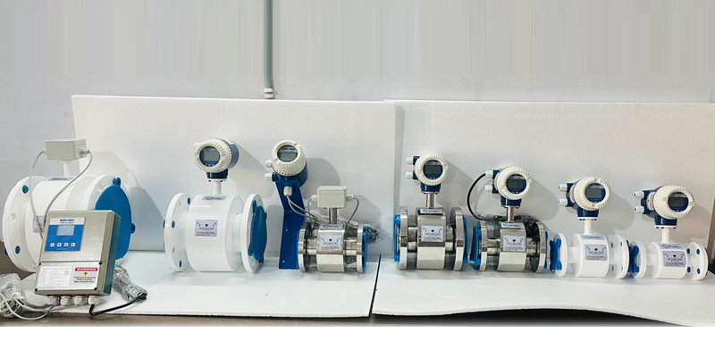
The electromagnetic flow meters in the AMAG-I Series are intended for measuring conductive liquids. With no moving parts and a PTFE lining, the AMAG-I mag meters can handle applications including wastewater, pulp, food, and slurries.
Installing an Electromagnetic Flow Meter
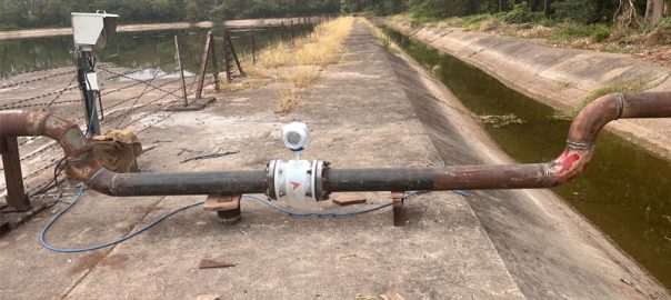
The magnetic flowmeter should always be filled with liquid. As a result, mag meters are best placed in vertical upward flow lines. If the pipe section is at a low place and the electrodes are not at the top of the pipe, installation in horizontal lines is permitted. This keeps air from making contact with the electrodes. When the process fluid is a slurry and the mag meter is mounted at a low point, solids should not settle and coat the internals during long periods of shutdown.
If it is necessary to drain the mag meter on a regular basis, an empty tube zero option should be offered. When this option is enabled, the transmitter’s output is capped at zero. Circuitry attached to extra sets of electrodes in the flow tube detects empty tube circumstances. An external contact, such as a pump status contact, can also activate the empty tube zero feature.
To maintain accuracy and reduce liner wear, mag meters need five diameters of straight pipe upstream and two diameters downstream. To shield the leading edge of the liners from the abrasive impacts of process fluids, liner protectors are supplied. The pipe should be supported on both sides of the mag meter if it is mounted in a horizontal pipe longer than 30 feet.
The magnetic flowmeter must be grounded to the process liquid electrically. This is because the mag meter is in the path of any stray current passing through the pipeline or the process liquid. Bonding creates a short circuit for stray currents, diverting them around the flow tube rather than through it, by grounding the meter at both ends of the process fluid. These currents can cause a zero shift in the magnetic flowmeter output if the system is not correctly grounded.
Metal ground straps are able to electrically bind to the process fluid. These straps join the flow tube’s two ends to the flanges of the nearby pipeline, which are in direct contact with the process liquid. When the piping is electrically conducting, straps are employed. Grounding rings are used for non-conductive or lined pipes. The interior diameter of the flow tube is the same as the nominal size (bore) of the grounding ring, which resembles an orifice plate. On the upstream and downstream sides, it is inserted between the flanges of the flow tube and the nearby process pipe. The flow tube is grounded by being hooked to a good conductor, such as a cold water pipe, and is coupled to the process fluid by being connected to the metallic grounding rings.


