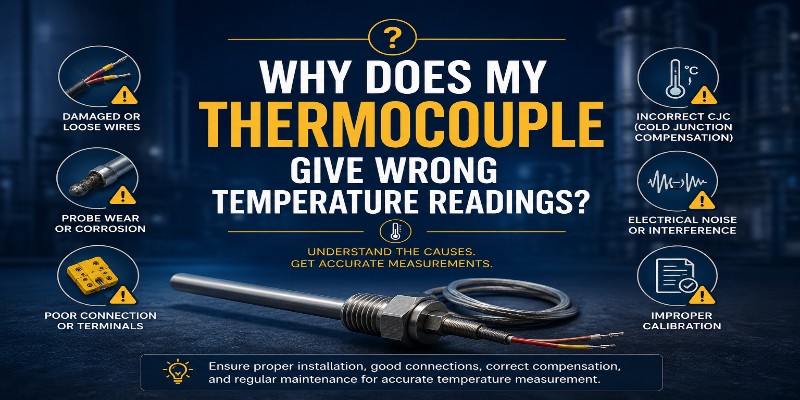
Why Does My Thermocouple Give Wrong Temperature Readings? 7 Causes + Solutions
By Aavad Instrument Pvt. Ltd. | Technical Support Division
You have invested in quality instrumentation. Your process is running. But the temperature controller is showing a reading that makes no sense — too high, too low, erratic, or stuck. Before you blame the controller or the process, the thermocouple is usually the first thing to investigate.
After manufacturing and servicing thousands of K type thermocouples for Indian industries, the Aavad Instrument engineering team has identified the 7 most common causes of wrong thermocouple temperature readings — and more importantly, how to fix them permanently.
Problem 1: Thermocouple Drift Due to Prolonged High-Temperature Exposure
What it looks like: Your K type thermocouple reads 50°C–100°C lower than the actual furnace temperature after months of operation.
Why it happens: At temperatures above 900°C, continuous exposure causes gradual changes in the crystal structure and chemical composition of Chromel and Alumel wires. This changes the EMF output — a phenomenon known as thermal drift. The green rot effect (selective oxidation of chromium in low-oxygen atmospheres between 800°C–1260°C) accelerates this problem.
Aavad Instrument Solution:
- Use Inconel 600 or SS 310 sheath material for applications above 900°C
- Specify duplex element (two independent sensors in one sheath) for critical processes
- Schedule annual NABL calibration to catch drift early
- Switch to N type thermocouple for continuous high-temperature operation above 1,100°C
Problem 2: Incorrect Extension Cable or Compensating Cable
What it looks like: Thermocouple reads correctly when tested on the bench but shows a constant offset of 20°C–80°C when installed in the field with long cable runs.
Why it happens: Connecting a K type thermocouple to a standard copper cable introduces an unwanted secondary thermocouple junction wherever the dissimilar metals join. This creates a phantom EMF that directly adds to or subtracts from your true reading.
Aavad Instrument Solution:
- Always use K type compensating cable (positive: yellow, negative: red as per IEC/ANSI)
- Match the cable type to the thermocouple type exactly — never mix J type cable with K type sensor
- Use Aavad K type thermocouple cable (SKU: AKES-AB) with fiberglass insulation for high-temperature runs
- For runs over 50 meters, use a head-mounted temperature transmitter (4–20 mA) to eliminate cable-induced errors entirely
Problem 3: Ground Loops and Electrical Interference (EMI/RFI Noise)
What it looks like: Temperature reading fluctuates wildly — jumping 30°C–200°C randomly, especially near variable frequency drives (VFDs), welding machines, or large motors.
Why it happens: The millivolt signal from a thermocouple is extremely sensitive. Nearby electrical equipment induces electromagnetic noise (EMI) or creates ground loops when the thermocouple sheath is grounded at multiple points.
Aavad Instrument Solution:
- Specify ungrounded (isolated) junction type thermocouple — prevents ground loop formation
- Use shielded, twisted-pair thermocouple extension cable
- Route thermocouple cables separately from power cables — minimum 300 mm separation
- Install a signal isolator / thermocouple transmitter at the head for clean 4–20 mA signal output to the PLC/DCS
Problem 4: Wrong Insertion Depth (Immersion Error)
What it looks like: Temperature reading is consistently lower than expected — by a small but repeatable amount, especially in pipes or vessels with high flow rates or significant heat loss.
Why it happens: If the thermocouple tip is not positioned at the thermal center of the medium, it measures a temperature that is influenced by conduction along the sheath toward the cooler connection head — known as stem conduction error or immersion error.
Rule of thumb: Insertion depth should be at least 10× the sheath OD. For a 6 mm sheath, the immersion depth should be minimum 60 mm.
Aavad Instrument Solution:
- Aavad engineers calculate insertion length based on your pipe/vessel size and process conditions
- Available in custom insertion lengths from 50 mm to 3,000 mm
- Thermowell installation guidance provided free with every head-type thermocouple order
Problem 5: Moisture Ingress and Insulation Resistance Failure
What it looks like: Reading fluctuates, or the thermocouple shows an open-circuit fault on the controller. Reading may appear close to ambient temperature even when process is at high temperature.
Why it happens: MgO insulation is hygroscopic — it absorbs moisture in humid or water-exposed environments. Once wet, insulation resistance drops dramatically, creating a shunt resistance that partially short-circuits the thermocouple signal.
Aavad Instrument Solution:
- Specify IP65 or IP67 weatherproof connection head for outdoor or humid installations
- Use hermetically sealed thermocouple heads near steam or washdown areas
- Select mineral-insulated (MI) thermocouple with welded-seal tip for the highest moisture protection
- Store spare thermocouples in dry, climate-controlled conditions — never in open warehouses
Problem 6: Reverse Polarity Connection
What it looks like: Controller reads a temperature far below ambient — for example, showing 10°C when the room is 30°C and the process is at 300°C.
Why it happens: The thermocouple connections are reversed — positive lead connected to negative terminal and vice versa. This causes the EMF signal to go in the wrong direction, resulting in a reading that decreases as temperature increases.
Quick Check: At ambient temperature (25°C), a correctly connected K type thermocouple should read close to ambient. If it reads below, swap the connections.
Aavad Instrument Solution:
- All Aavad thermocouples are colour-coded per IEC 60584 with clearly marked +/− terminals
- K type: Positive (+) = Yellow/Green, Negative (−) = White/Red
- Free wiring diagram shipped with every thermocouple
Problem 7: Using Wrong Thermocouple Type for Controller Setting
What it looks like: All connections are correct, installation is proper, but readings are consistently off by a non-linear amount across the temperature range.
Why it happens: If a K type thermocouple is connected to a controller set for J type (or any other type), the controller uses the wrong mV-to-temperature conversion table, producing incorrect readings at all temperatures.
Aavad Instrument Solution:
- Always verify the instrument input type matches the thermocouple type
Head Type Thermocouple Manufacturer , Wire Type RTD & Thermocouple Sensor Manufacturer
- K type is the most universal — supported by virtually all temperature controllers, PLCs, SCADA systems, and data loggers
- Aavad provides free application support to help configure your controller correctly
Summary — Quick Diagnosis Table
| Symptom | Most Likely Cause | Quick Fix |
|---|---|---|
| Reading too low, consistent offset | Drift, immersion error | Recalibrate / increase insertion depth |
| Constant offset (20–80°C) | Wrong extension cable | Replace with K type compensating cable |
| Random fluctuation, spikes | EMI/Ground loop | Isolated junction + shielded cable |
| Below ambient reading | Reverse polarity | Swap +/− connections |
| Open circuit fault | Broken wire, moisture | Replace thermocouple |
| Wrong reading at all temps | Controller type mismatch | Set controller to K type input |
📞 Facing unresolved temperature measurement issues? Call Aavad Instrument’s technical helpline: +91 90996 22823