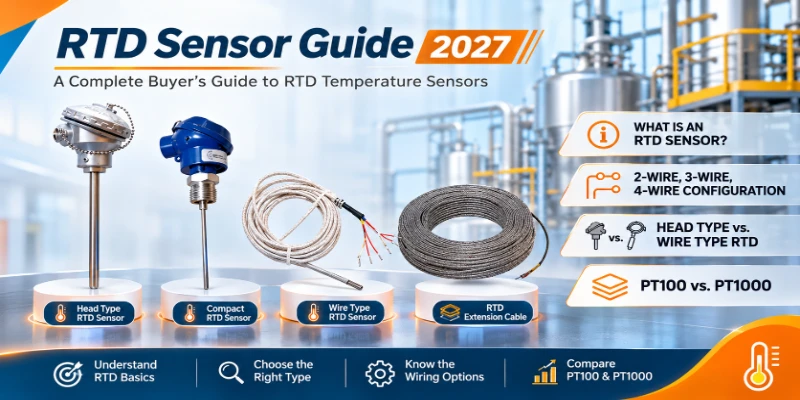
A temperature probe is easy to ignore until it misbehaves. Then a reading drifts, a batch is rejected or a furnace trips for no reason, and the first questions are always the same: which sensor was fitted, and how was it wired? An RTD sensor measures temperature by tracking how the electrical resistance of a platinum element rises with heat. It is the standard choice between -200 °C and 850 °C (-328 °F to 1,562 °F) when repeatable accuracy, long-term stability and standard calibration matter. This guide answers those questions before they cost you anything.
What Is an RTD Sensor and How Does It Work?
An RTD sensor, also called Resistance Temperature Detector or platinum resistance thermometer (PRT), is a passive temperature probe whose platinum element changes electrical resistance predictably as temperature changes. A standard PT100 reads 100.00 ohms at 0 °C (32 °F) and 138.51 ohms at 100 °C (212 °F), which lets a transmitter or PLC calculate the temperature.
Platinum is the industrial standard because it resists corrosion and follows a near-linear resistance curve. IEC 60751 sets the Temperature Coefficient of Resistance (TCR) at 0.00385 Ω/Ω/°C, so a PT100 gains about 0.385 ohms per 1 °C (about 0.214 ohms per 1 °F). An RTD makes no voltage of its own. The instrument passes a small excitation current through the element, typically 1 mA or less, and measures the voltage drop. Explore the full resistance temperature detector range for industrial use.
The Callendar-Van Dusen equation describes the full curve. Above 0 °C, Rt = R0 (1 + At + Bt²), where R0 is the resistance at 0 °C, A = 3.9083 × 10^-3 per °C and B = -5.775 × 10^-7 per °C². Below 0 °C a third coefficient, C = -4.183 × 10^-12 per °C⁴, is added to account for the curve at low temperatures.
What Is the PT100 and PT1000 Resistance Table (IEC 60751)?
A PT100 reads 100.00 ohms at 0 °C and 390.48 ohms at 850 °C. A PT1000 reads exactly ten times those values across the whole span. Technicians use the table below to check a probe with a digital multimeter before replacing a sensor or recalibrating a transmitter.
PT100 and PT1000 resistance versus temperature (IEC 60751, TCR 0.00385)
| Temperature | PT100 Resistance | PT1000 Resistance |
|---|---|---|
| -200 °C (-328 °F) | 18.52 Ω | 185.2 Ω |
| -100 °C (-148 °F) | 60.26 Ω | 602.6 Ω |
| 0 °C (32 °F) | 100.00 Ω | 1,000.0 Ω |
| 50 °C (122 °F) | 119.40 Ω | 1,194.0 Ω |
| 100 °C (212 °F) | 138.51 Ω | 1,385.1 Ω |
| 150 °C (302 °F) | 157.33 Ω | 1,573.3 Ω |
| 200 °C (392 °F) | 175.86 Ω | 1,758.6 Ω |
| 300 °C (572 °F) | 212.05 Ω | 2,120.5 Ω |
| 400 °C (752 °F) | 247.09 Ω | 2,470.9 Ω |
| 500 °C (932 °F) | 280.98 Ω | 2,809.8 Ω |
| 600 °C (1,112 °F) | 313.71 Ω | 3,137.1 Ω |
| 850 °C (1,562 °F) | 390.48 Ω | 3,904.8 Ω |
Check whether older plant instruments use the standard IEC 60751 curve (0.00385) or an older curve such as 0.00392 before ordering replacement elements. A curve mismatch produces a steady offset that looks like a faulty probe.
What Is the Difference Between 2-Wire, 3-Wire and 4-Wire RTD Configurations?
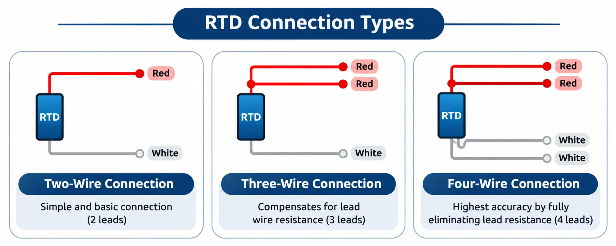
A 2-wire RTD uses one conductor pair and adds cable resistance straight into the reading. A 3-wire RTD adds a compensation lead so a Wheatstone bridge can cancel matched wire resistance. A 4-wire RTD separates the excitation pair from the voltage-sensing pair and removes lead resistance error entirely.
How Does a 2-Wire RTD Perform?
Excitation current and voltage measurement share the same two wires. On a PT100, 1 ohm of total lead resistance adds about 2.6 °C (4.7 °F) of error. Use a 2-wire probe only on short cable runs or for non-critical monitoring.
How Does a 3-Wire RTD Cancel Lead Resistance?
The third conductor places both measuring leads in opposite arms of a Wheatstone bridge, so their resistances cancel. The cancellation holds when the leads share the same length, gauge and temperature exposure. This is the standard choice for process plants, PLCs and DCS inputs.
How Does a 4-Wire RTD Remove Lead Error?
Two outer leads carry the excitation current while two inner leads measure the element voltage through a high-impedance input that draws almost no current. Cable resistance and temperature gradients along the cable drop out of the result. Laboratories and custody transfer measurements rely on it. For loops that need two independent signals, specify a 4-wire duplex RTD.
RTD wiring configurations compared
| Wiring Type | Lead Resistance Compensation | Measurement Accuracy | Best Application |
|---|---|---|---|
| 2-wire | None, lead resistance adds to the reading | Lowest | Short runs, HVAC, PT1000 loops |
| 3-wire | Bridge cancels matched lead resistance | High (standard) | Process plants, PLC and DCS loops |
| 4-wire | Full elimination | Highest | Class A and AA service, laboratories, runs over 10 m (33 ft) |
What Is the Difference Between a Head Type RTD Sensor and a Wire Type RTD Sensor?
A head type RTD sensor ends in a terminal head that holds a ceramic terminal block, which allows easy field wiring and replacement of the insert without disturbing the process piping. A wire type (cable) RTD sensor has an insulated lead cable leaving the sheath directly, and it suits compact or vibrating installations.
What Are the Features of a Head Type RTD Sensor?
Head type assemblies suit fixed vessels, pipelines and thermowells. Heads come as weatherproof designs with IP65 or IP67 ingress protection, flameproof designs for hazardous areas, and miniature designs, in stainless steel, neoprene, hinge type or plastic. Cable entry is single or double, and the ceramic terminal block is straight or spring loaded. Browse the head type RTD sensor range and the wire type RTD temperature sensor models.
What Are the Features of a Wire Type RTD Sensor?
Wire type probes fit machinery bores, bearing housings, surface pads and mobile equipment where a terminal head cannot go. Shapes include straight, L-shape, square, washer, leaf, flexible extension and fixed bayonet, with lead insulation in Teflon (PTFE), fiberglass, PVC or silicon rubber. A pencil type RTD sensor suits tight bores, and the waterproof RTD PT100 temperature sensor suits washdown zones. Pair high-heat runs with a PTFE RTD extension cable.
Head type versus wire type RTD sensor
| Parameter | Head Type RTD Sensor | Wire Type (Cable) RTD Sensor |
|---|---|---|
| Electrical termination | Ceramic terminal block inside a protective head | Integral insulated lead cable |
| Primary mounting | Thermowells, pipes, reactors, storage tanks | Surfaces, motor windings, bearings, tight bores |
| Maintenance | Insert swaps without unwiring the field cable | Whole assembly is replaced as one unit |
| Environmental protection | Weatherproof or flameproof head | Set by sheath seal and cable jacket |
| Best fit | Fixed process piping and hazardous areas | Compact, vibrating or space-constrained points |
What Are the Key Differences Between PT100 and PT1000 RTD Sensors?
Both follow the IEC 60751 platinum curve (TCR 0.00385) but differ tenfold in base resistance: a PT100 reads 100 ohms at 0 °C and a PT1000 reads 1,000 ohms. Because a PT1000 changes by about 3.85 ohms per °C, cable resistance causes ten times less error in a 2-wire circuit.
In practice, PT100 is the standard for industrial transmitters, DCS cards and process controllers, thanks to wide hardware support and lower self-heating at standard excitation currents. A PT1000 sensor excels in 2-wire HVAC loops, building automation and battery-powered data loggers, where 1 ohm of lead resistance shifts the reading by only 0.26 °C (0.47 °F) instead of 2.6 °C. Specialty elements such as PT-200, PT-500, PT-2000, CU-53 and NI-100 exist for older instrument inputs.
PT100 versus PT1000
| Technical Parameter | PT100 | PT1000 |
|---|---|---|
| Resistance at 0 °C (32 °F) | 100.00 Ω | 1,000.0 Ω |
| Resistance at 100 °C (212 °F) | 138.51 Ω | 1,385.1 Ω |
| Sensitivity | About 0.385 Ω/°C | About 3.85 Ω/°C |
| 2-wire lead error per 1 Ω | About 2.6 °C (4.7 °F) | About 0.26 °C (0.47 °F) |
| Self-heating at equal current | Lower | Higher (ten times the power) |
| Typical domain | Process plants, refineries, pharma, OEM skids | HVAC, energy meters, battery loggers, 2-wire runs |
What Are the IEC 60751 RTD Accuracy Classes and Temperature Ranges?
IEC 60751 classifies platinum RTD accuracy into four tolerance grades: Class AA, Class A, Class B and Class C. Tolerance is written as ±(a + b × t) in °C, where t is the temperature without its sign. Class B (±0.30 °C at 0 °C) serves general control, and Class A (±0.15 °C at 0 °C) serves tighter process tolerances.
Each class applies only within a stated temperature window, which depends on whether the element is wire-wound (wider range) or thin-film (compact and vibration resistant). Operating a probe outside its window removes the class guarantee. Class A and AA probes should always use 3-wire or 4-wire circuits, so cable resistance does not swamp the sensor precision.
IEC 60751 tolerance classes for Pt100 (t = temperature in °C, without sign)
| Class | Tolerance Formula (°C) | At 0 °C | At 100 °C | Wire-wound Range | Thin-film Range |
|---|---|---|---|---|---|
| AA | ±(0.10 + 0.0017 × t) | ±0.10 °C (±0.18 °F) | ±0.27 °C (±0.49 °F) | -50 to 250 °C | 0 to 150 °C |
| A | ±(0.15 + 0.0020 × t) | ±0.15 °C (±0.27 °F) | ±0.35 °C (±0.63 °F) | -100 to 450 °C | -30 to 300 °C |
| B | ±(0.30 + 0.0050 × t) | ±0.30 °C (±0.54 °F) | ±0.80 °C (±1.44 °F) | -196 to 600 °C | -50 to 500 °C |
| C | ±(0.60 + 0.0100 × t) | ±0.60 °C (±1.08 °F) | ±1.60 °C (±2.88 °F) | -196 to 600 °C | -50 to 600 °C |
| 1/3 DIN | One third of the Class B tolerance | ±0.10 °C (±0.18 °F) | ±0.27 °C (±0.49 °F) | Set by manufacturer | Set by manufacturer |
The 1/3 DIN label is a manufacturer designation that matches Class AA at 0 °C. Confirm its valid range on the datasheet before ordering. See the combined RTD and thermocouple sensor range for other options.
How Do Sheath Material, Construction and Junction Affect Performance?
Sheath alloy decides which fluids and temperatures a probe survives. Construction decides how it copes with vibration and bending, and the junction decides speed and electrical isolation.
Sheath material guide
| Sheath Material | Typical Use | Note |
|---|---|---|
| SS 304 | General water, air and mild media | Common low-cost choice |
| SS 316 and SS 316L | Chemical, food, pharma and marine service | 316L suits welded assemblies |
| SS 310 | High-temperature oxidising atmospheres | Check the maximum temperature on the datasheet |
| Inconel 600, Inconel 800 and Incoloy 800 | High heat and oxidation | For furnaces and heat treatment |
| Hastelloy C | Aggressive acids and chlorides | Confirm against fluid data |
| Tantalum | Strong acid service | Confirm against fluid data |
| Teflon coated | Corrosive chemicals at moderate temperature | Coating limits the maximum temperature |
| Silicon carbide and silicon nitride | Abrasive and high-temperature duty | Ceramic, so avoid mechanical shock |
- Mineral Insulated (MI) construction packs compressed magnesium oxide around the conductors. It tolerates tight bending radii and resists vibration better than rigid bar stock or straight tubes.
- Ungrounded junctions isolate the element from the sheath and prevent ground-loop interference. Grounded junctions respond faster. Exposed tips respond fastest, but only in clean, dry streams.
How Does an RTD Sensor Compare With a Thermocouple and a Thermistor?
An RTD sensor gives the best accuracy, linearity and long-term repeatability below about 600 °C (1,112 °F). A thermocouple measures temperatures up to 1,800 °C (3,272 °F) with faster response and rugged durability. A thermistor gives high sensitivity over a narrow band, roughly -50 °C to 150 °C, at low cost.
RTD versus thermocouple versus thermistor
| Selection Factor | RTD (PT100 / PT1000) | Thermocouple (Types K, J, S, B) | NTC / PTC Thermistor |
|---|---|---|---|
| Operating principle | Platinum resistance change | Thermoelectric voltage between two metals | Semiconductor resistance change |
| Temperature range | -200 to 850 °C | -200 to 1,800 °C | About -50 to 150 °C |
| Accuracy and drift | Highest accuracy, low drift | Moderate, drifts at high heat | Good in a narrow band |
| Signal linearity | Near linear (IEC 60751) | Nonlinear, needs cold junction compensation | Strongly nonlinear |
| Response speed | Moderate | Fast | Fast |
| Best fit | Process control, pharma, food, calibration | Furnaces, kilns, exhausts | HVAC, appliances, consumer electronics |
Aavad Instrument manufactures both families, so a project that needs RTDs and thermocouples can run on one specification and one set of certificates.
How Fast Does an RTD Respond, and What Causes Measurement Errors?
Thermal response time is the time a probe needs to register 63.2% of a sudden temperature step. One manufacturer publishes about 5 to 7 seconds for a direct-immersion 6.35 mm (1/4 inch) stainless sheath and 15 to 20 seconds inside a thermowell. Four installation errors erode the datasheet accuracy:
- Self-heating. Keep transmitter excitation at 1 mA or less, never above 5 mA, so I²R power does not warm the platinum element in still gas.
- Insufficient immersion depth. A common rule of thumb is to immerse at least 10 times the sheath diameter plus the element length, so heat conduction along the stem does not pull the reading toward the pipe wall.
- Uncompensated lead resistance. Pair Class A and AA probes with 3-wire or 4-wire inputs, or fit a head-mounted 4-20 mA transmitter that removes long-cable error.
- Moisture ingress. Water in the head or sheath lowers insulation resistance and causes erratic downward drift, so seal cable glands and head gaskets properly.
How Do You Select the Right RTD Sensor? (5-Step Engineering Checklist)
- Define the temperature span and tolerance class. Note normal and upset temperatures, then check that the chosen class holds across the whole window: Class B for general loops, Class A for tight control, Class AA or 1/3 DIN for custody transfer.
- Select the wire configuration and element. Choose a 3-wire PT100 for standard industrial loops, a 4-wire PT100 for Class A or AA service or cable runs over 10 metres (33 feet), and a 2-wire PT1000 for short HVAC or battery circuits.
- Choose head type or wire type construction. Use a head type assembly for fixed piping and thermowells, and a wire type probe for machinery bores, surfaces and high-vibration points.
- Match the sheath alloy and process fitting. Pair SS316L, Inconel or Hastelloy C with the process media, and confirm the thread: 1/8″ to 2″ in BSP or NPT, compression fitting, flange or Triclover.
- Verify thermowell and transmitter compatibility. Confirm the thermowell bore fits the sheath, and that your PLC or transmitter supports the element curve and wire count. Browse the configurable process temperature sensor options for ready assemblies.
How Do You Write a 15-Point RTD Sensor Purchase Specification?
Copy the list below into your enquiry and fill in every line. A complete specification removes the back-and-forth that delays most quotations.
- Element type: PT100, PT1000 (or PT-200, PT-500, PT-2000, NI-100, CU-53).
- Tolerance class: Class B, Class A, Class AA or 1/3 DIN.
- Junction type: ungrounded, grounded or exposed.
- Sheath material: SS 316, SS 316L, SS 310, Inconel 600 or 800, Hastelloy C, tantalum or Teflon coated.
- Sheath construction: Mineral Insulated (MI flexible), straight tube or bar stock.
- Element configuration: simplex, duplex, triplex or multipoint.
- Wiring configuration: 2-wire, 3-wire or 4-wire per element.
- Terminal head or termination: weatherproof, flameproof, miniature (stainless steel, neoprene or plastic) or wire-type lead.
- Cable entry: single or double (for example M20 x 1.5 or 1/2″ NPT).
- Terminal block or transmitter: straight or spring-loaded ceramic block, or a 4-20 mA head-mounted transmitter.
- Process connection: adjustable compression fitting, fixed fitting, flange, Triclover, nipple-union or weld pad.
- Fitting size and thread: 1/8″, 1/4″, 3/8″, 1/2″, 3/4″, 1″, 1.5″ or 2″, in BSP or NPT.
- Probe dimensions: sheath outer diameter (for example 3 mm, 6 mm or 8 mm) and immersion length in mm and inches.
- Lead cable, if wire type: cores (2, 3, 4, 6 or 8), insulation (PTFE, fiberglass, PVC or silicon rubber) and colour code (IEC, ANSI or DIN).
- Quantity and certification: order quantity, calibration certificate (0 °C, 100 °C or multi-point) and delivery destination.
Send the completed list to the Aavad temperature sensor team for a matched technical quotation.
How Do You Troubleshoot a Faulty RTD Sensor?
When an RTD shows an off-scale reading, slow drift or a fixed offset, disconnect the probe from the transmitter and measure resistance across the terminals with a calibrated multimeter. Compare the result with the resistance table above.
- Infinite resistance (open circuit, off-scale high): a broken element wire, a fractured internal lead or a loose terminal screw.
- Resistance far below expected (short circuit, off-scale low): a crushed MI sheath, a pinched lead cable or moisture bridging the ceramic terminal block.
- Gradual downward drift: moisture inside the sheath or head, which lowers insulation resistance below the datasheet limit (commonly 100 MΩ).
- Constant fixed offset: uncompensated cable resistance in a 2-wire circuit, or the wrong curve setting in the controller (0.00392 instead of 0.00385).
- Ice-bath check: put the probe tip in a stirred crushed-ice and distilled-water slush at 0.0 °C. A healthy PT100 reads 100.00 Ω within its class tolerance.
What Are the Most Common RTD Sensor Questions?
What Is the Maximum Temperature Range of an RTD Sensor?
Standard industrial platinum RTDs operate from -200 °C to +850 °C (-328 °F to +1,562 °F) under IEC 60751. The exact limit for a probe depends on its element construction (wire-wound or thin-film), sheath alloy and lead cable insulation.
How Do You Choose Between PT100 and PT1000 for Industrial Automation?
Choose PT100 for process plants, DCS and PLC systems and higher temperatures, because instrument support is universal and self-heating is lower. Choose PT1000 for 2-wire HVAC loops, energy meters and battery-powered loggers, where the higher base resistance reduces cable error and power draw.
How Do You Decide Between a 4-Wire and a 3-Wire RTD?
Specify a 4-wire RTD when the job needs Class A or AA precision, when cable runs exceed 10 metres (33 feet), or when extension wires pass through uneven ambient temperatures that weaken 3-wire cancellation. Confirm that the input card supports a true 4-wire measurement first.
How Do You Use an RTD Sensor in High-Vibration Pipelines?
Specify a Mineral Insulated (MI) sheath with a thin-film platinum element and a spring-loaded insert inside a heavy-duty thermowell. Compressed magnesium oxide insulation protects the internal conductors from fatigue under continuous vibration.
How Do You Choose an RTD Sensor Manufacturer?
Ask each candidate to state the element, tolerance class, sheath, wiring and head on the quotation, and to confirm the thread, dimensions and certificates in writing. Our guide to choosing an RTD sensor manufacturer in India lists eight questions to ask before you order.
What Makes Aavad Instrument a Good Source for Custom-Built RTD Sensors?
Aavad Instrument Private Limited manufactures RTD assemblies and matched extension cables built to your process dimensions, thread standard (BSP or NPT) and IEC 60751 accuracy class. That removes the catalogue compromises that OEMs and process plants often face.
How Do You Get an RTD Sensor Quotation From Aavad Instrument?
Send your 15-point specification to Aavad Instrument and receive a matched technical quotation. Include the element and class, wiring, sheath diameter and material, immersion length, head and cable entry, process connection and thread, and the calibration certificate you need.
If a drawing or a sketch is easier, send that instead. Not sure yet which supplier to trust? Read how to compare an RTD sensor manufacturer in India first, then come back with your specification.
Ready to order? Contact Aavad Instrument with your specification and get your RTD sensor quotation today.